Controlling my ceiling fan from Home Assistant with 433Mhz RF Modules
As is required when you become a dad, I recently got into home automation. I installed Home Assistant and integrated it with the few smart devices I had in my apartment. But one of the things I really wanted to control from my smartwatch (Home Assistant has a great Wear OS app) was the ceiling fan in my bedroom. Unfortunately my fan did not support being controlled via app or over Wifi or anything like that. Since I already dabbled in electronics, and inspired by my role model Wayne Szalinski (fictitious inventor dad from the "I Shrunk the Kids" movies) I decided to experiment with transforming my ceiling fan into a smart device.

My fan did come with an old-fashioned remote control that constantly got lost between our mattress and bedpost. The remote can turn the fan on and off, set different spin speeds, and also turn the bedroom lights on and off. I wondered if I could control the fan from Home Assistant by using a microcontroller to mimic the signals emitted by the remote.
Understanding how the remote works 🧑🏫
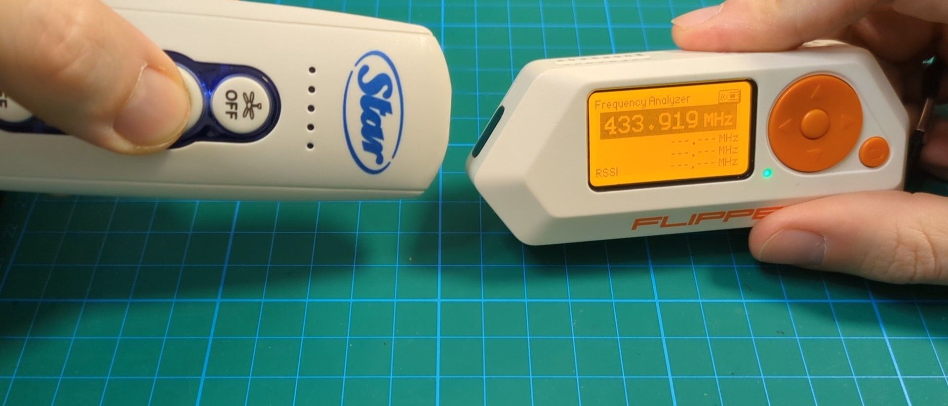
I assumed the remote transmits over radio frequency (RF). I could validate this with my Flipper Zero. I was able to capture the signal from the original remote, then replay it using the Flipper Zero. Crucially, the Flipper can also pinpoint the specific frequency used by the remote. All I needed to do was fire up the Frequency Analyzer tool and press one of the remote's buttons. As you can see, it looks like the remote is using the 433MHz frequency:
So I went on Aliexpress and searched for an RF module uses that frequency. I ended up purchasing this kit which includes 5 transmitters and 5 receivers for $5.
Prototyping with a breadboard 🧑🔬
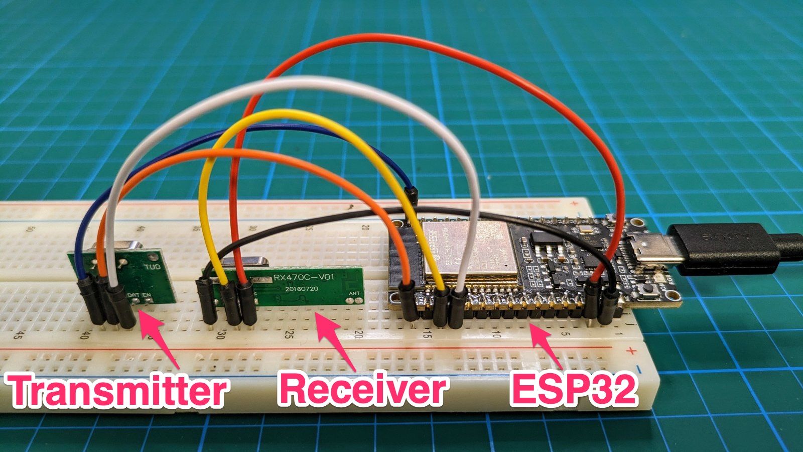
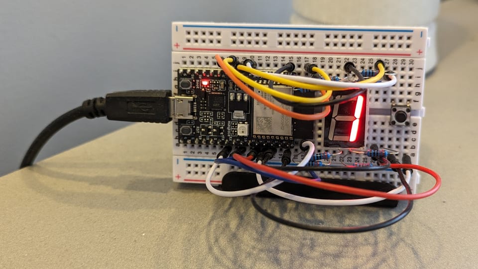
Now that I had the RF modules, it was time to see if I could capture the remote's signal using the receiver, and replay that signal using the transmitter. I connected both modules to an ESP32 microcontroller using a breadboard and some jumper cables.
| RF Module | ESP32 board | |
|---|---|---|
| Receiver | VCC | 5v |
| GND | GND | |
| Data | GPIO 4 | |
| Transmitter | + | 3v3 |
| - | GND | |
| Data | GPIO 5 | |
In terms of code, I looked for an Arduino\ESP32-compatible library to control 433MHz RF modules and found that rc-switch seemed to be the de-facto standard.
Capturing signals
To capture the signal that is sent when each remote button is pressed, I flashed the ESP32 using the example sketch provided by rc-switch called ReceiveDemo_Advanced.ino (github). It prints out all the information about the detected signal. The only change I had to make to the original sketch was to specify that data was coming in on GIPO 4:
-mySwitch.enableReceive(0);  // Receiver on interrupt 0 => that is pin #2
+mySwitch.enableReceive(digitalPinToInterrupt(4));
This video shows how as I'm pressing buttons on the original remote, the captured signal data is printed out to the Serial Monitor:
For example, when I click the "Light on" button this is what gets printed out:
Decimal: 11207696 (24Bit)
Binary: 101010110000010000010000
Tri-State: not applicable
PulseLength: 456 microseconds
Protocol: 6
Raw data: 10455,446,685,451,...
What's important to note here is mainly the Decimal value. This represents the specific "code" that is sent when this particular button is pressed.
Replaying signals
Now that I've captured the codes that match each remote button press, I didn't really need the receiver module anymore. Instead my focus became to make the transmitter send these codes. The rc-switch library comes with an example sketch called SendDemo.ino (github) that shows how to send codes. Based on it, I created my own sketch that will turn the lights on, wait 1 second, turn the lights off, wait 1 second, and repeat ad infinitum.
#include <RCSwitch.h>

RCSwitch mySwitch = RCSwitch();

void setup() {
  mySwitch.enableTransmit(digitalPinToInterrupt(5));
  mySwitch.setProtocol(6);
  mySwitch.setPulseLength(456);
}

void loop() {
  mySwitch.send(11207696, 24);
  delay(1000);
  mySwitch.send(11207904, 24);
  delay(1000);
}
I flashed this sketch to my board and moved the prototype to my bedroom. To my delight the lights flickered on and off! 🎉🥳
Integrating with Home Assistant 🏠
Next I wanted to be able to transmit RF signals on demand via Home Assistant. This is why it's important I used an ESP32 board rather than a standard Arduino board, as the ESP32 has an integrated Wi-Fi module so I would be able to access it on my local home network. I decided to use the MQTT Protocol for communication between Home Assistant and the ESP32 board. I would publish commands from Home Assistant over the bedroom-fan topic, and subscribe to those messages from the ESP32 board.
Handling commands from the ESP32 board
First I needed to understand how to connect to my home Wifi network from the ESP32 board. I followed the examples from the arduino-esp32 project, specifically the HelloServer.ino example sketch (github). And in order to subscribe to MQTT topics I downloaded the PubSubClient library (created by Nick O'Leary the creator of Node-RED) and followed their mqtt_basic.ino example (github).
Here's the final version of my sketch. It connects to Wifi, sets up an MQTT subscription, and when a new message is received it replays the correct RF code:
#include <RCSwitch.h>
#include <WiFi.h>
#include <PubSubClient.h>
#include <map>

const char* mqttTopic = "bedroom-fan";
std::map<String, unsigned long> messageCodes = {
  {"light-on", 11207696},
  {"light-off", 11207904},
  {"fan-off", 11207824},
  {"fan-speed-low", 11207872},
  {"fan-speed-medium", 11207744},
  {"fan-speed-high", 11207808}
};

WiFiClient espClient;
PubSubClient client(espClient);
RCSwitch mySwitch = RCSwitch();

void setup() {
  Serial.begin(115200);

  setupRcSwitch(5, 6, 456);
  setupWifi("ssid", "password");

  client.setServer("homeassistant.local", 1883);
  client.setCallback(callback);
}

void sendRadioCommand(const String& message) {
  if (messageCodes.find(message) != messageCodes.end()) {
    mySwitch.send(messageCodes[message], 24);
  } else {
    Serial.println("Received an unrecognized message");
  }
}

void setupRcSwitch(int pin, int protocol, int pulseLength) {
  mySwitch.enableTransmit(digitalPinToInterrupt(pin));
  mySwitch.setProtocol(protocol);
  mySwitch.setPulseLength(pulseLength);
}

void setupWifi(const char* ssid, const char* password) {
  WiFi.mode(WIFI_STA);
  WiFi.begin(ssid, password);

  while (WiFi.status() != WL_CONNECTED) {
    delay(500);
    Serial.print(".");
  }
  Serial.println("");
  Serial.print("Connected to ");
  Serial.println(ssid);
  Serial.print("IP address: ");
  Serial.println(WiFi.localIP());
}

void reconnect() {
  while (!client.connected()) {
    Serial.print("Attempting MQTT connection...");
    if (client.connect("ESP32Client")) {
      Serial.println("connected");
      client.subscribe(mqttTopic);
    } else {
      Serial.print("failed, rc=");
      Serial.print(client.state());
      Serial.println(" try again in 5 seconds");
      delay(5000);
    }
  }
}

void callback(char* topic, byte* payload, unsigned int length) {
  Serial.print("Message arrived [");
  Serial.print(topic);
  Serial.print("] ");

  String message = "";
  for (int i = 0; i < length; i++) {
    message += (char)payload[i];
  }
  Serial.println(message);

  sendRadioCommand(message);
}

void loop() {
  if (!client.connected()) {
    reconnect();
  }
  client.loop();
  delay(2); // allow the CPU to switch to other tasks
}
It's worth noting that the ESPHome project supports sending 433MHz RF signals via its Remote Transmitter configuration, so this could be another way of making your ESP board react to commands from Home Assistant and send RF codes accordingly.
Issuing commands from Home Assistant
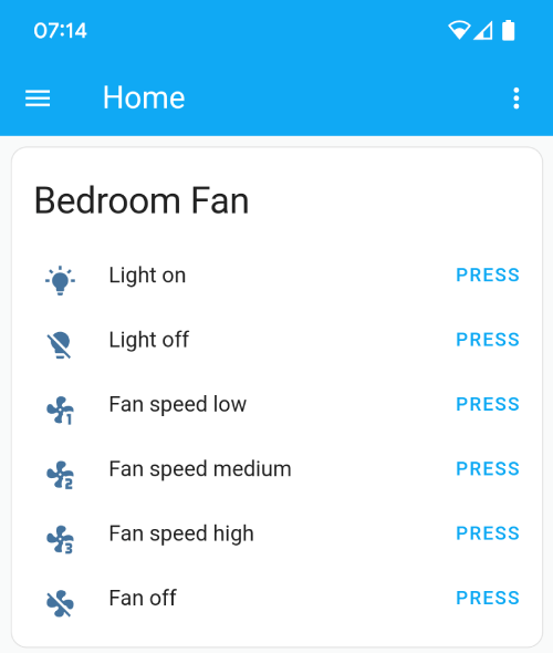
I added the MQTT integration to Home Assistant to be able to publish messages from Home Assistant. I then used the Template helper in my configuration.yaml to create buttons for each action and specify which MQTT message to send when each action is invoked.
template:
  - button:
      - name: "Light on"
        icon: "mdi:lightbulb-on"
        press:
          service: mqtt.publish
          data:
            topic: bedroom-fan
            payload: light-on
      # Add the rest of the button mapping here...
      # You can find the list of available icons here https://pictogrammers.com/library/mdi/
Once Home Assistant is aware of these buttons it's possible to add them to my main dashboard:
Demo time ✨
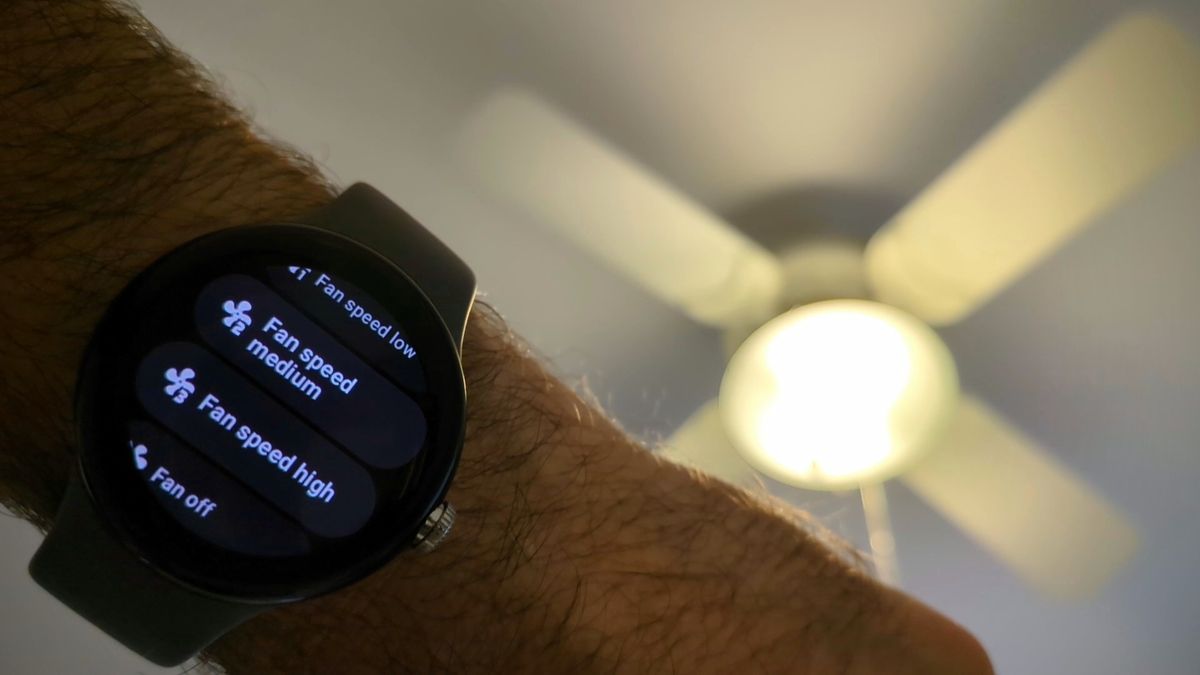
After all this work, here's me controlling my fan from my watch!
It's working! 🚀
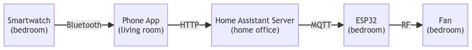
It's funny to think about the long "trip" that each command does and the protocol used in each step:
Making it permanent 👷
Once I had this working I was essentially done. I could technically place the prototype anywhere in my bedroom and start controlling the fan from my smartwatch\phone. But the breadboard is quite bulky and the connections aren't sturdy. So I set out to create a permanent device that's small and reliable.
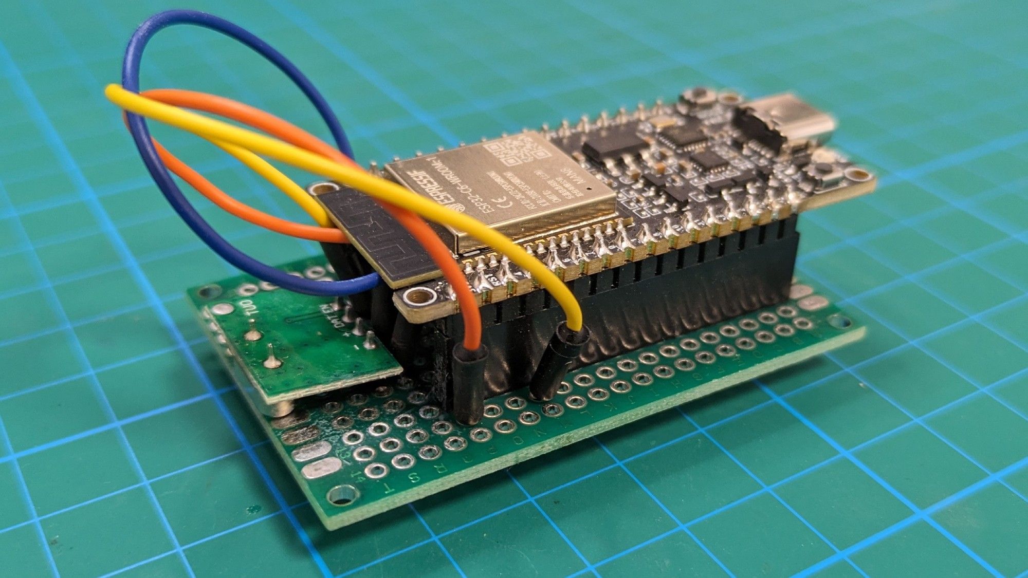
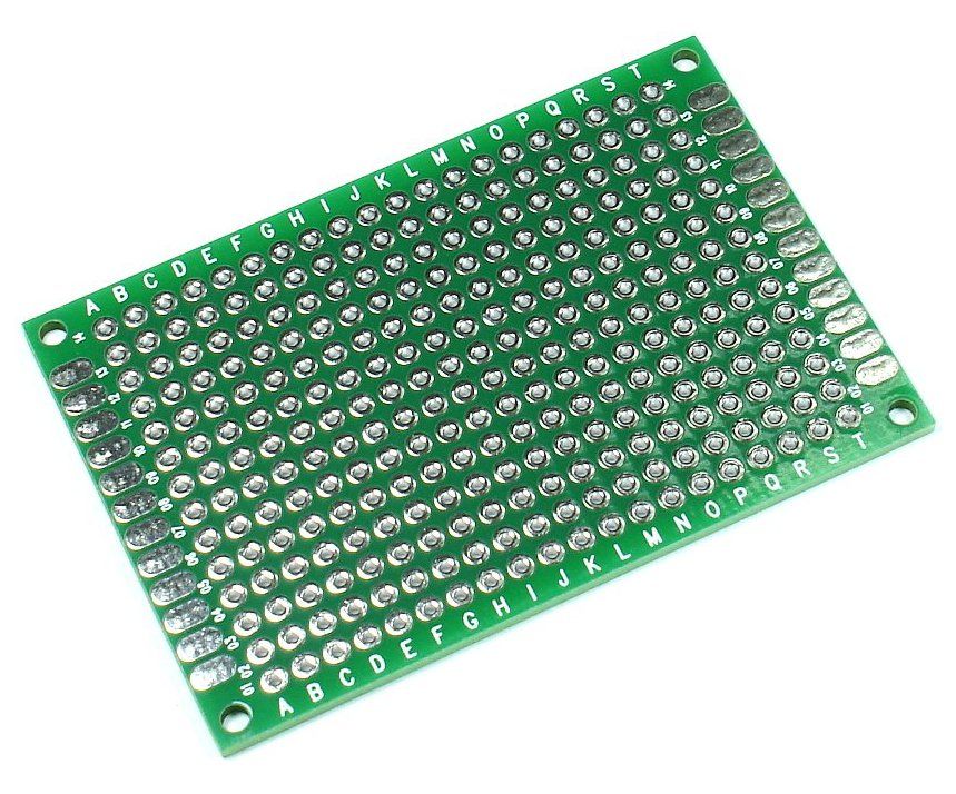
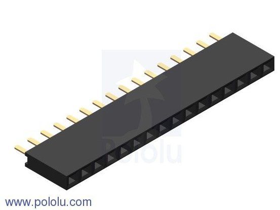
To achieve this I moved the ESP32 board and the transmitter from the breadboard to this small perfboard and soldered the components together. Instead of soldering the ESP32 board directly to the other components, I placed it on top of these headers so I could detach it easily if needed. Here's what it looked like after soldering:
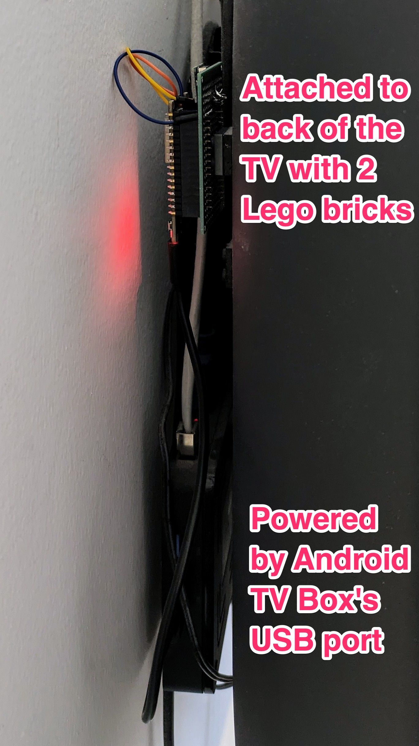
In terms of finding a permanent place for the device in my bedroom, I needed to find a spot that's out of sight and doesn't take up any space, but still close enough to the ceiling fan for the transmitter's small antenna to be effective, and close to a power supply. I ended up mounting it to the back of my TV. I already had a small Android TV Box behind there which had a free USB port I could use for power. I super-glued a small 4x4 lego piece to the back of the TV, and another identical lego piece to the back of the device. By connecting the two lego pieces the device stays firmly attached to the TV, but if needed could be easily detached.
Wrapping things up 🎀
That's the end of my home automation adventure for now. Although I'm inspired by another role model of mine to get into 3d-printing and to design a proper enclosure for this device.
If you have thoughts \ feedback \ questions about this post I'd love to hear from you. Feel free to reach out on Twitter.