Transforming an Arcade Machine into a WFH-friendly Grafana Dashboard
Like a lot of people, in the past couple of months I've been working from home. One of the things I missed about working from an office is having a dedicated monitor that cycles through graphs showing the latest metrics about the services that our team owns. One day as I was thinking about this I looked around my home-office and I spotted a Wix Engineering-branded Mini-Arcade machine that was collecting dust on my desk (I'm not much of a gamer). It occurred to me that its small screen could be perfect for presenting graphs, and that I could even use the physical buttons to navigate through them. Luckily, despite having no idea how an arcade machine works, I managed to modify it to display graphs from Grafana. In this post I'll explain how to transform a Mini-Arcade machine like the one I had into a customizable always-on display, so you can keep track of the things you care about with a glance. Don't worry if you've never tinkered with electronics or used a soldering-iron before. I didn't either before starting this project.
Skip to Part 6 if you just want to start building.
Part 1: Arcade machine tear-down 🛠
(to understand how it works)
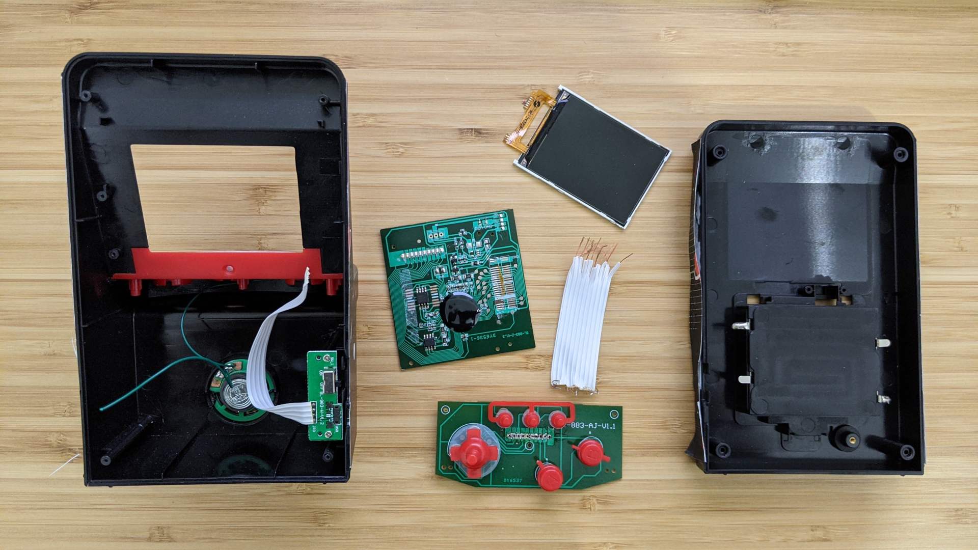
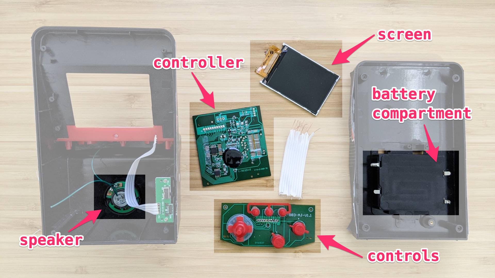
Luckily, since the Mini-Arcade machine I had was swag from the company I work at, a few of my co-workers had a spare machines that weren't in use as well. This allowed me to take one completely apart to study its parts and how they work, without worrying about putting it back together. Here's a photo of what it looks like torn apart. See if you can figure out what each part does, and then use the slider to see if you got it right.
Part 2: Planning the transformation 📝
Now that I understood how the arcade machine works I needed to figure out what parts I need to get and how to put them together.
I knew the modified version will have to have these capabilities:
- Access to the Internet
- Always-on
- Programmable
Based on these requirements I decided to use a Raspberry Pi Zero as the "brains" of the new machine. It can connect to the internet wirelessly, and when the Pi itself is powered-on it can power the screen and the controls. I could try to re-use the original screen but I would have to learn to reverse-engineer how to control it so I decided to get rid of it and try to find a screen with the same form-factor that's designed to be controlled by a Raspberry Pi. This meant that other than the plastic exterior, the only original part I would need to re-utilize are the physical buttons and the circuit-board that controls them.
Part 3: Learning how the controls works 🕹
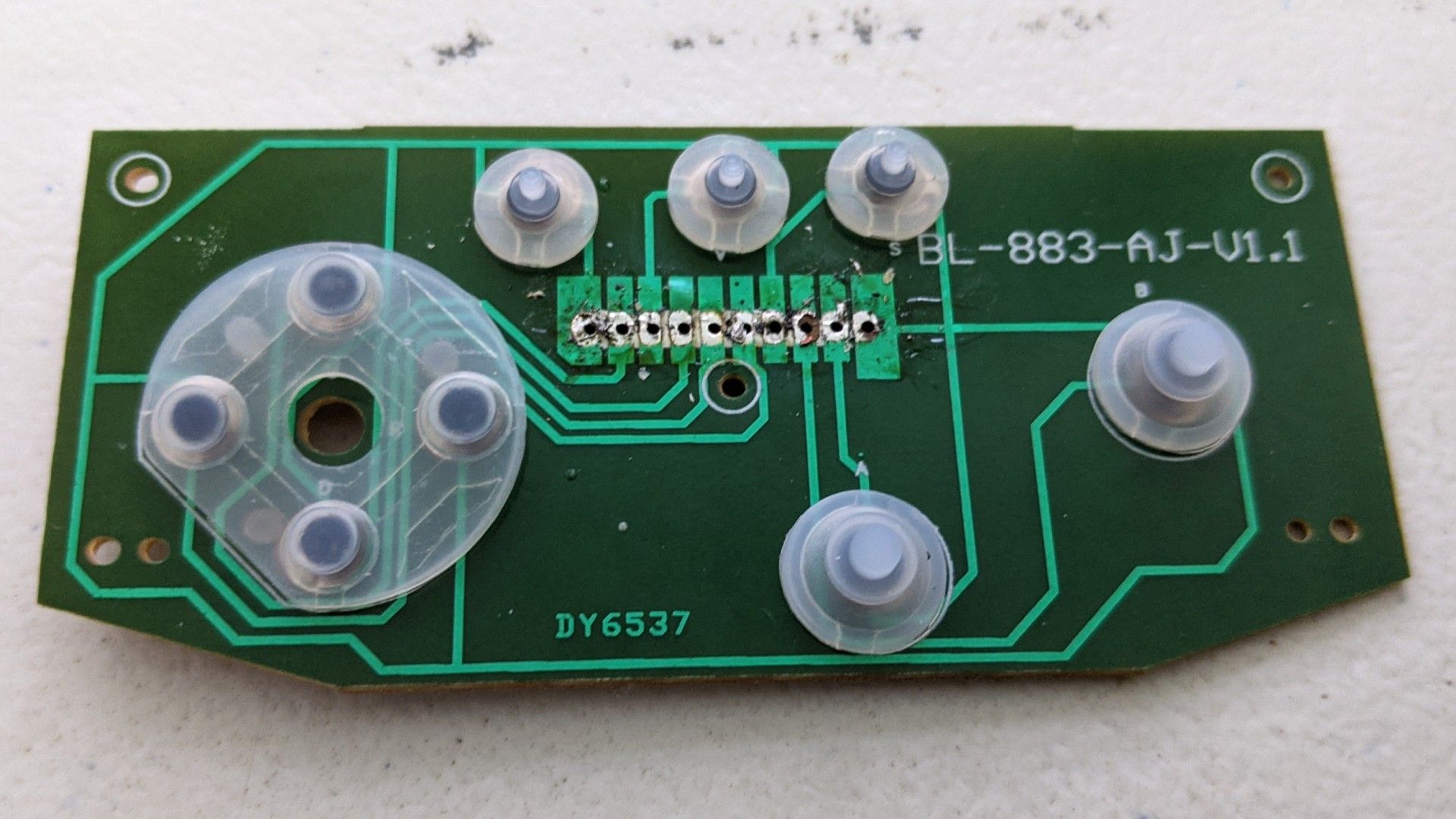
The photo below shows the circuit-board that controls the buttons. The series of 10 pins that you can see in the center were connected via a ribbon cable to the main controller of the arcade machine. I assumed that each pin controls one of the buttons but there were 9 physical buttons and 10 pins 🤔. See if you can figure out what's the responsibility of each pin, and then use the slider to see if you got it right.
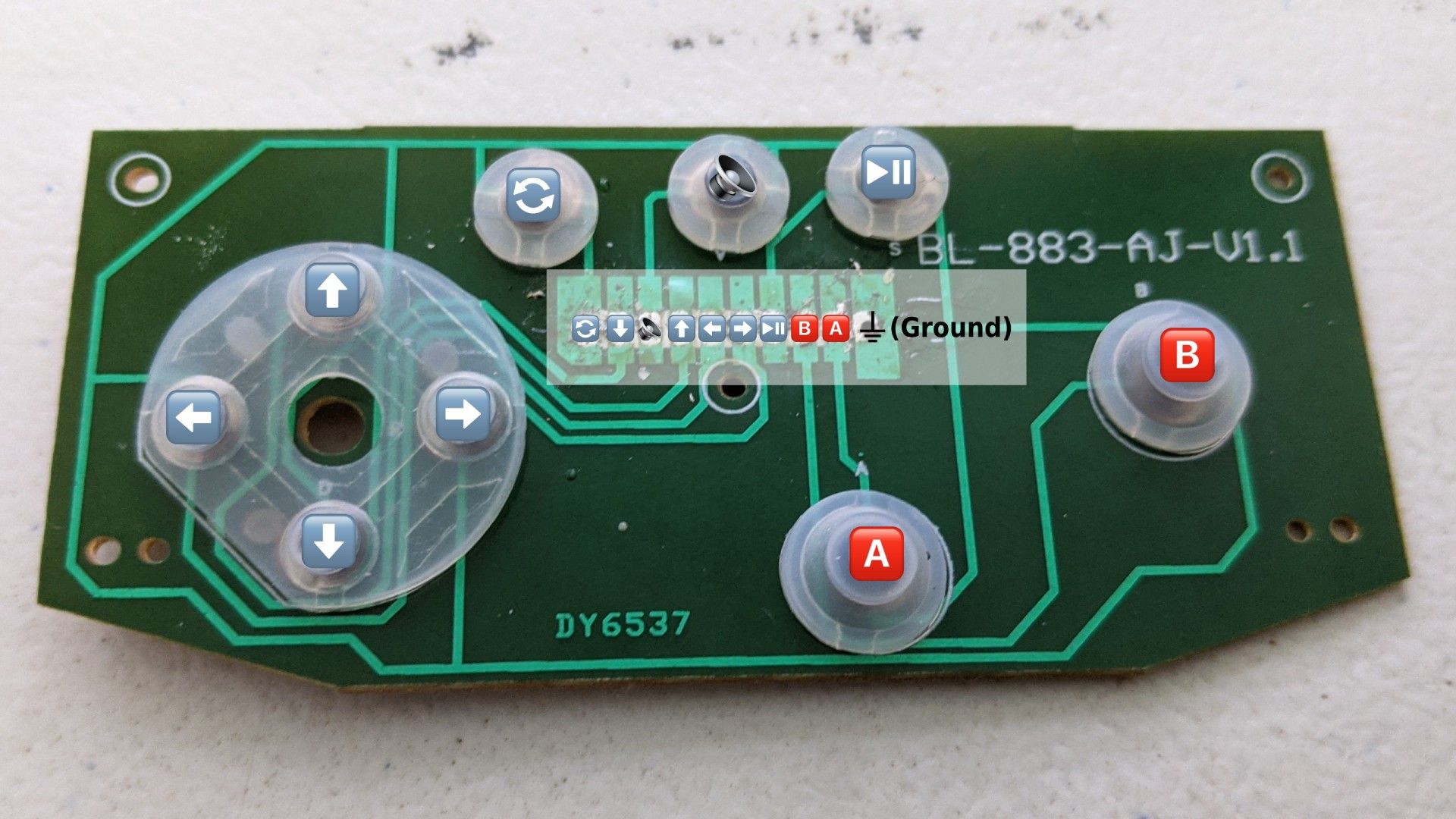
I noticed that each pin is connected via a light-green path that's printed on the board to one of the physical buttons. This gave away which pin is associated to which button. In addition, all the buttons are connected via a single printed path to the right-most pin. This made me realize that this is the Ground pin that closes the electrical circuit. When you push a button it closes the circuit it's connected to, and that changes the signal on the pin that's connected to that button. This means that we'll connect the right-most pin to the Ground (GND) on the Pi, and each other pin to one of the Pi's GPIO pins. This will allow us to react to the user pushing the button that's connected to that pin. To make sure I got it right I used alligator clips to connect a Rasbperry Pi to one of the buttons, and followed this example to write a tiny Node.js script to console.log when the button is pressed. Here's a demo showing this in action:
Part 4: Controlling the display 🖼
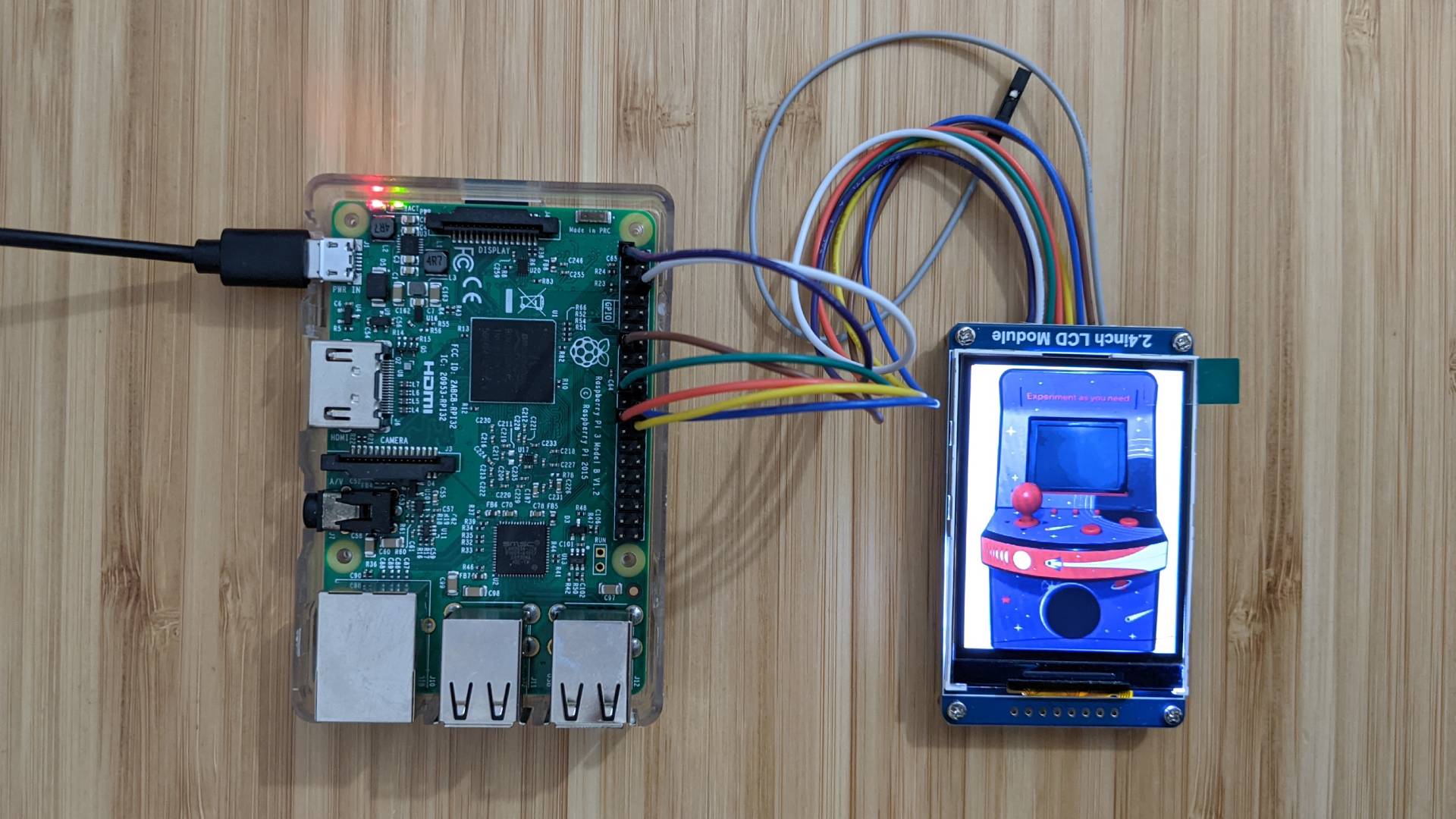
I picked up this screen because it's 2.4" inches like the original screen. If you click the "Raspberry Pi Guides" tab here it explains how to connect the screen to the Pi, and explains how to download and install a Python display driver for it. I didn't want to use Python so I ended-up porting the Python code to Javascript. I released the code in npm under rpi-ili9341-lcd. In the github repo you can find examples of how to use it together with some popular Node.js image manipulation libraries.
To make sure that everything is working correctly I connected the screen to a Raspberry Pi and verified that I can set the image from code using the library I wrote.
Part 5: Planning how to wire the components together 🧑🏭
Here's how I planned to connect the Pi pins to the controllers and screen:
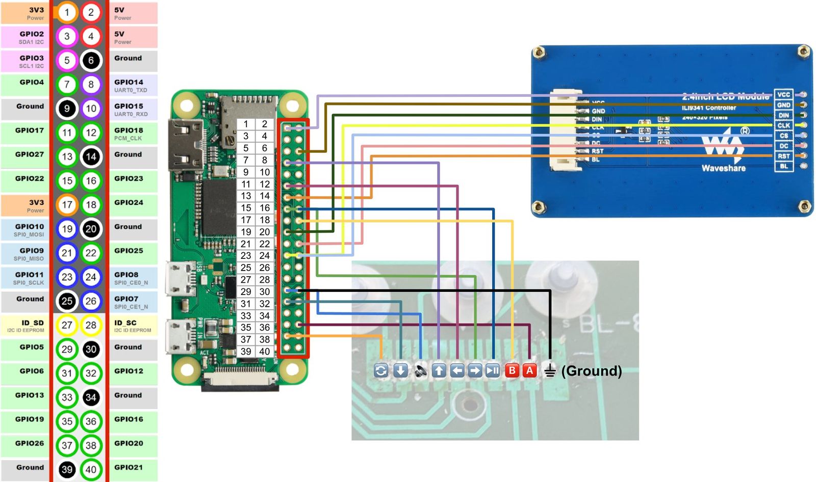
Part 6: Putting it all together
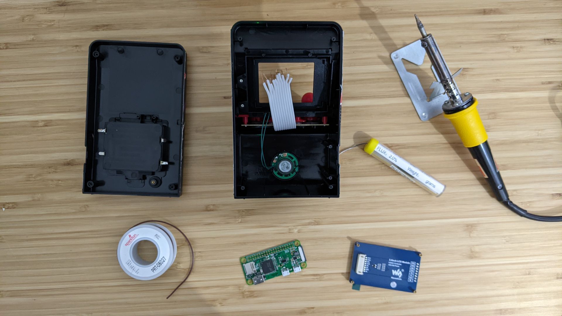
Once I was confident that I knew how to control the buttons and the screen, I was ready to start building my dashboard machine. Here are the parts and tools I used:
Parts 🕹
- Mini-Arcade machine
The one I got as a gift had no discernible manufacturer\model info, but it looks to be the same model as this one. - Raspberry Pi Zero
With WiFi (either built-in or via a USB Dongle), and a power-supply. - 2.4" LCD Module
This model matched the form-factor of the original screen on my arcade machine. - Pin headers
- Wires
Tools 🧰
- Soldering kit (soldering-iron, solder, solder wick)
- Wire Stripper
- Hot-glue gun
A note on soldering
I've never soldered anything before and it was a bit intimidating at first. But I watched some youtube videos to learn how to do it, and ultimately it wasn't that difficult (although I definitely recommend picking up some solder wick which removes solder if when you make mistakes).
Process
Here's a video showing most of the build process:
- Remove the back screws and open up the arcade machine (carefully)
- Remove the parts we don't need (the original screen, original controller, the on\off switch)
- Expose the wires on the ribbon that connects to the controllers
- Solder the Raspberry Pi to the controllers via the exposed ribbon
- Solder the Raspberry Pi to the screen (using extra wires)
- Use the hot-glue gun to glue the screen in place (while being careful to put the glue only on the parts of the screen that are behind the plastic exterior)
- Connect the power-supply to the Micro USB port on Raspberry Pi and run it through the spot where the on\off switch was (this will let you seal the machine back up without needing to drill a special hole to run the cable through)
- Seal it back up
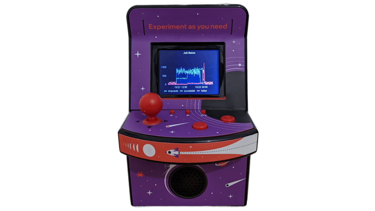
The Grafana Dashboard is ready! ✨
Et voilà, here is the Grafana Dashboard in action:
P.S. what about the software? 🧑💻
Let me know if you're interested in a follow-up post about the software that's running on the Raspberry Pi, or if you want me to put the code up on Github.